
Leave A Message
If you are interested in our products and want to know more details,please leave a message here,we will reply you as soon as we can.

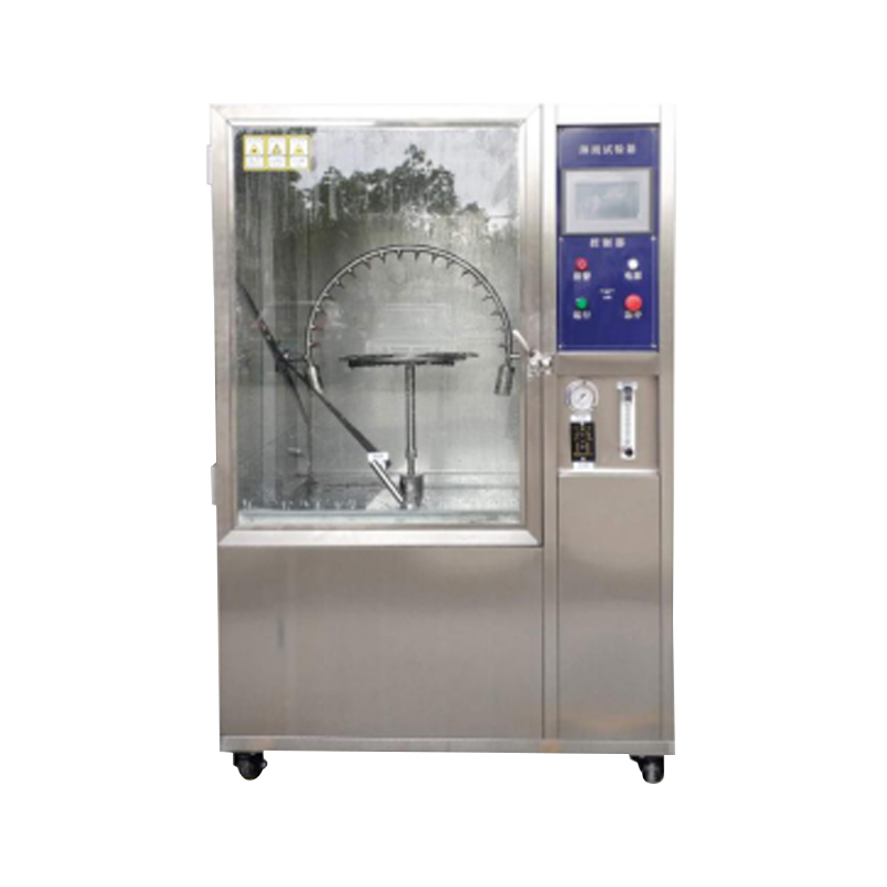
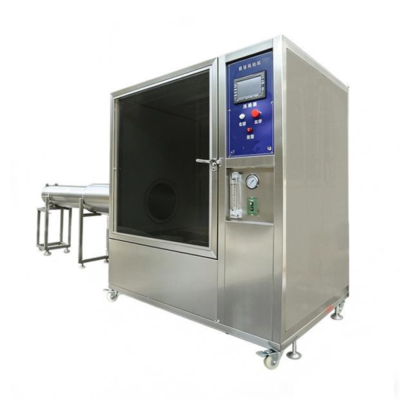
This IPX56 Waterproof Test Chamber is mainly used to evaluate the performance of products under simulated rain conditions during storage, transportation, and use. It is widely applied to electrical and electronic products, lighting equipment, electrical cabinets, electrical components, automobiles, motorcycles, and their parts.
Item No :
GT-F63Order(MOQ) :
1
Under simulated rainfall conditions, the IPX56 Test Chamber tests the physical and other related properties of the products. After testing, the results are assessed to determine whether the product meets the required standards, providing a basis for product design, improvement, verification, and factory inspection.
A water tank is installed at the bottom. Water is pumped and pressurized by a stainless steel water pump inside the right-side control cabinet, then delivered to the spray nozzles on the side spray pipe system. The nozzle sprays water horizontally onto the sample placed on the turntable, and the water then flows back into the water tank, forming a water circulation system. The pump outlet is equipped with control components such as a flow meter, pressure gauge, and solenoid valve. A waterproof turntable is installed inside the inner chamber, and its rotation speed is controlled via the control panel.
GB-4208-2008, GB2423.38, IPX5, IPX6 protection levels
| Model | GT-F63-500 | GT-F63-1000 |
| Capacity | 500L | 1000L |
| Turntable Diameter | 400 mm | 600mm |
| Turntable Load Capacity chamber | 20 kg | |
| Number of Spray Nozzles | IPX5 nozzle, 1pc; IPX6 nozzle, 1pc (2 in total) | |
| Water Exposure Surface | Side of the product | |
| Distance from Nozzle to Sample | 2,500-3,000mm | |
| Nozzle Inner Diameter | IPX5: φ6.3 mm; IPX6: φ12.5 mm | |
| Spray Flow Rate | IPX5: 12.5 ± 0.625 (L/min); IPX6: 100 ± 5 (L/min) | |
| Pipe Diameter | One 1/2" and one 1" high-pressure flexible hose | |
| Spray Pressure | 30–200 kpa (adjustable according to flow rate) | |
| Turntable Speed | 1–7 rpm | |
| Spray Duration | 3, 10, 30, 9,999 min (adjustable) | |
| Operation Time Control | 1–9,999 min (adjustable) | |
1. Ambient Temperature
RT 10–35°C (Average temperature over 24 hours ≤ 28°C)
2. Ambient Humidity ≤ 85% RH
3. Power Supply
380V 50Hz, three-phase five-wire with protective ground; grounding resistance of protective wire < 4 Ω.
Users are required to install an air circuit breaker or power switch of appropriate capacity at the installation site; this switch must be a dedicated, independent circuit reserved exclusively for this equipment.
4. Power Approx. 4 kW
5. Protection System
Protection against leakage, short circuit, water shortage, motor overheating and alarm notifications
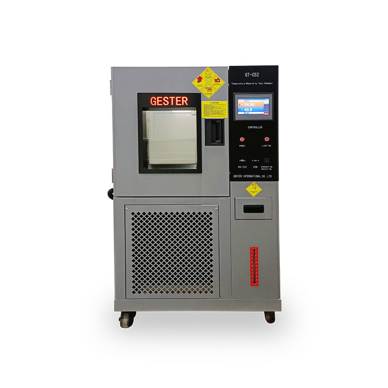
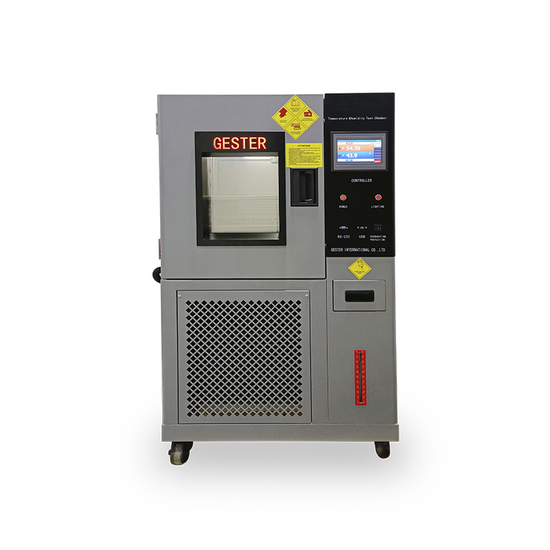
High-Precision Climate Simulation for Reliable Material & Electronic Reliability Testing -This constant temperature humidity chamber features programmable control, wide temperature and humidity ranges, and complies with international standards. Main Features: ✔ Wide Testing Range: Temperature: -60°C to +150°C | Humidity: 20% to 98% RH. ✔ Smart Control: 7-inch programmable color touch screen controller with USB data export. ✔ Premium Components: Equipped with imported French Tecumseh compressor. ✔ International Standards: Fully complies with ISO, ASTM, IEC, JIS, BS.
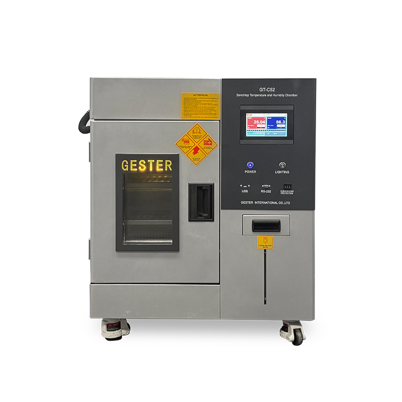
Benchtop temperature and humidity test chamber delivers precise environmental control through stable temperature and humidity settings for conditioning of samples prior to testing. Its compact footprint allows it to be easily placed on a stand or workbench, perfectly suiting laboratories and testing areas where space is limited — without compromising build quality or testing performance.
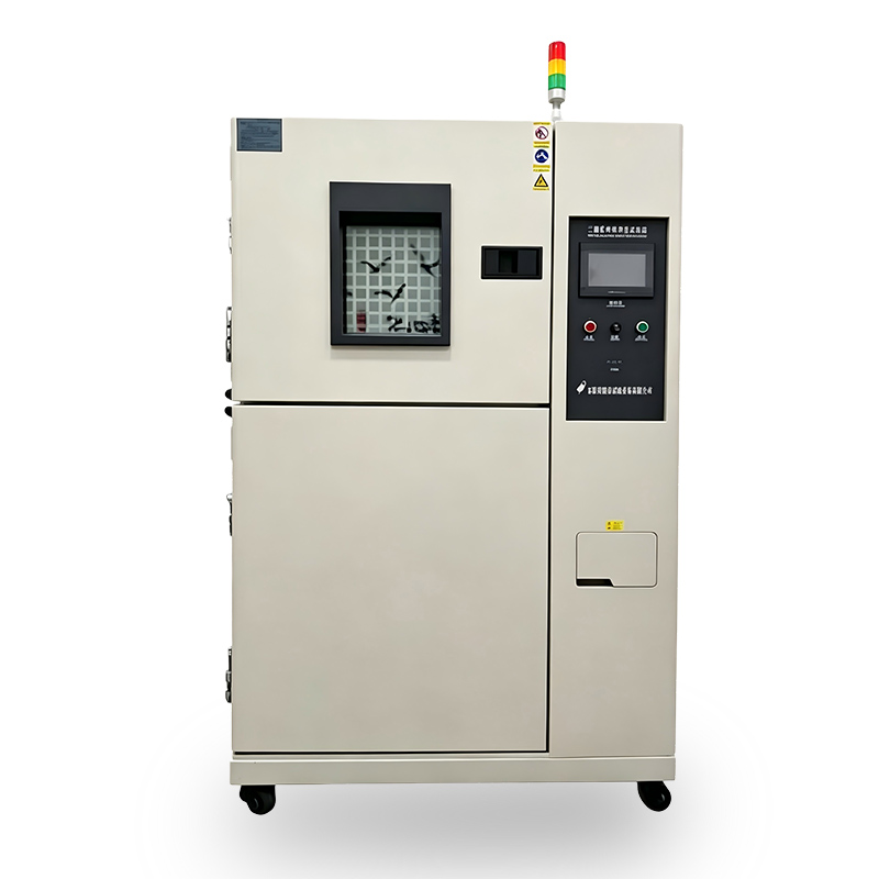
Thermal Shock Test Chamber consists of two independent compartments. The thermal shock machine or material being tested is placed in a test basket or tray and then transferred between the hot and cold chambers. The transfer process is rapid, ensuring quick temperature changes that simulate real-world conditions. This enables manufacturers to evaluate the impact of temperature differentials on product integrity, performance, and reliability.
High Low Temperature Test Chamber is devices specifically designed to simulate extreme high- and low-temperature environments, enabling the assessment of the durability, functionality and performance of materials and components following prolonged exposure. Ideal for material durability testing in electronics, aerospace, and industrial applications.
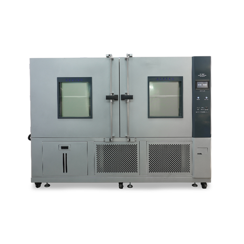
Walk In Environmental Test Chamber, suitable for test instrumentation materials, electricians, electronic products, household appliances, auto parts, chemical coatings,various electronic components and parts of other related products are stored and transported under high temperature and low temperature environment. The adaptability test is used to evaluate its performance indexes.
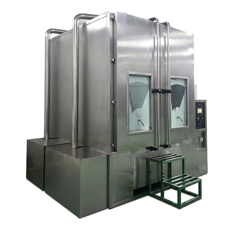
Walk in Dust Test Chamber provide a simulated sand blowing and dusting environment. It can continuous operation for a long time without failure. Sand and dust chamber Standards GB 4208, GB/T 2423.37, IEC60529, ISO 20653, BS 60598, DIN 40050-9, UL and such relevant standards
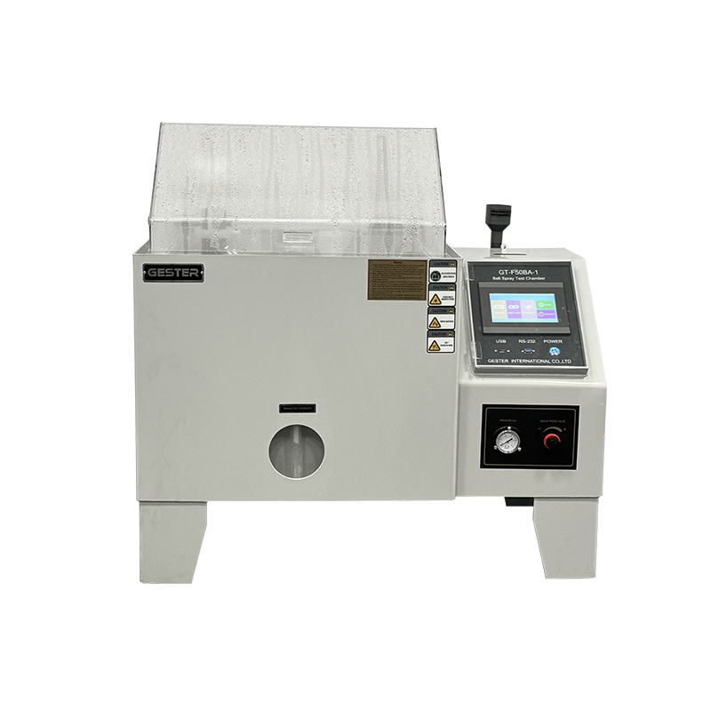
Salt spray test chamber is essential for evaluating the corrosion resistance of metals, coatings, and other materials – ensuring that products meet stringent corrosion resistance standards and enhancing their reliability in real-world applications.
The rain test chamber is used to test the rainproof and waterproof performance of products. GESTER Rain Test Machine can precisely control test conditions, ensuring compliance with industry standards and improving product reliability.
IP Rain Spray Test Chamber adopts a scientific design that enables the equipment to realistically simulate various environments such as dripping, raining, splashing, and spraying. While meeting national standards, the Rain Test Equipment offers stable performance in all aspects and is highly practical and easy to control.
GESTER IPX Rain Test Chamber offers high precision and reliability, ensuring compliance with international standards and providing an efficient solution for testing under simulated rain spray conditions.
This IPX56 Waterproof Test Chamber is mainly used to evaluate the performance of products under simulated rain conditions during storage, transportation, and use. It is widely applied to electrical and electronic products, lighting equipment, electrical cabinets, electrical components, automobiles, motorcycles, and their parts.
The IPX Chamber is designed to simulate water immersion conditions and assess. GESTER IPX7 Water Soaking Test Chamber can provide custom-made immersion tanks to suit your specific requirements. This flexibility ensures accurate and reliable results for each tested product.
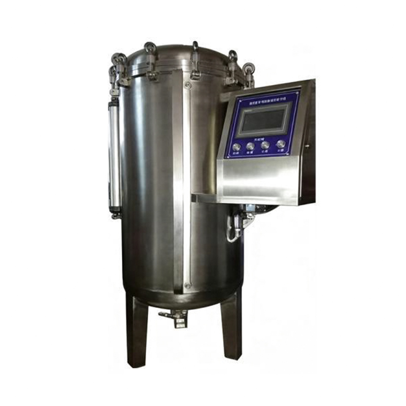
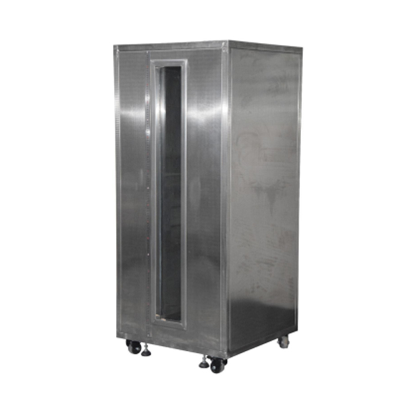
IPX78 Water Immersion Test Chamber is a device used to test the waterproof performance of a product. IPX78 Immersion Pressure Test Device is usually made of stainless steel with well-sealed structure. It can simulate the water pressure and immersion conditions under different water depths and time to simulate the waterproof performance in the actual use environment.
This IPX6K Test Chamber is mainly used for testing the physical and other related properties of electronic and electrical products, lamps, electrical cabinets, electrical components, automobiles, motorcycles and their parts under simulated rainy weather conditions.
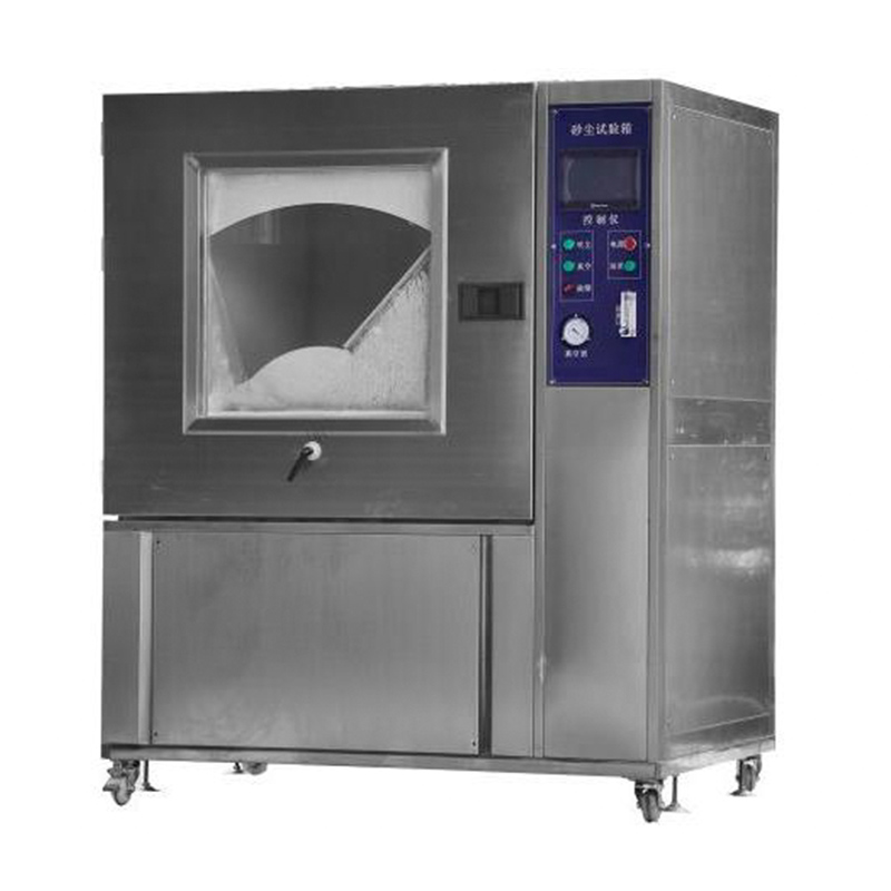
GESTER sand and dust test chamber is a device specifically designed to evaluate the effects of sand and dust particles on various products. It provides a controlled environment that allows products to undergo rigorous testing to determine their resistance to particle ingress and to assess their overall performance in dusty, dusty conditions.
leave a message
Scan to wechat :

Scan to Whatsapp :