Leave A Message
If you are interested in our products and want to know more details,please leave a message here,we will reply you as soon as we can.

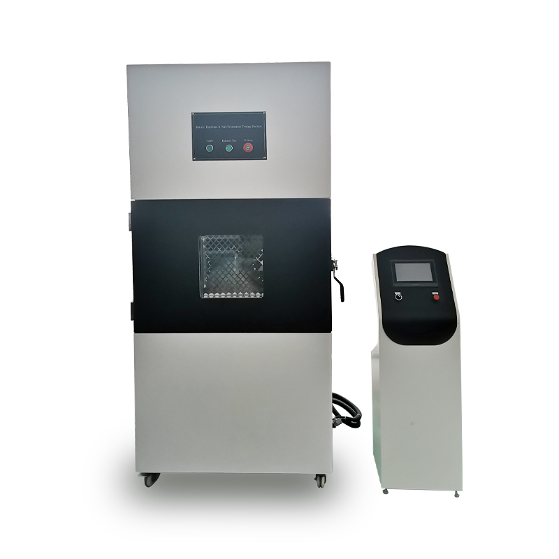
The battery short-circuit tester is designed according to the requirements of various battery short-circuit test standards.
According to the standard, the short-circuit device must meet the internal resistance range of 80mΩ±20 or ≤10mΩ to obtain the maximum short-circuit current required by the test.
This Battery short-circuit tester is used to simulate the external short circuit of the battery or battery pack/battery pack sample, and judge its safety through its phenomenon.
Item No :
GT-I09Order(MOQ) :
1
The short-circuit tester adopts PID control to simulate the external short circuit of batteries, complying with UL1642, UN38.3, IEC62133, GB/T18287, GB/T 31241-2014 and other standards. It uses contactors as switching elements and thermal relays as protection devices; the tested battery circuit is short-circuited when the circuit breaker is closed, with a strong short-circuit current passing through the entire circuit.
The battery surface temperature, voltage and current signals detected by Hall elements are processed by data processing, and the software records the changes of battery voltage, current and surface temperature continuously.
The Battery Short Circuit Testing Machine must ensure that the total resistance of the entire circuit (including circuit breakers, wires and connectors) is (80±20)mΩ, and each circuit can withstand a peak short-circuit current of 500A.
Optional short-circuit stop mode: Short-circuit duration.
· GB31241-2022 Safety Requirements for Lithium-Ion Batteries and Battery Packs for Portable Electronic Products
· GB/T36276-2018 Lithium-Ion Batteries for Electrical Energy Storage
· GB/T36972-2018 Lithium-Ion Storage Batteries for Electric Bicycles
· IEC62133-2012
· UL1642
· UN38.3
High Temperature External Short Circuit
Fully charge the battery according to the specified test method, connect the positive and negative terminals of the battery with a wire and ensure the total external resistance is (80±20)mΩ at the same time; place the battery in an environment of 57℃±4℃, and keep it for another 30min after the battery temperature reaches 57℃±4℃. The battery surface temperature can be monitored during the test. The test shall be terminated when one of the following conditions is met:The short-circuit duration reaches 24 hours.
Acceptance Criterion: The battery shall not catch fire or explode
|
Model |
GT-I09 |
|
|
Maximum testing voltage |
500V |
|
|
Dc response time |
≤5μs |
|
|
Maximum short circuit current |
0-1000A |
|
|
The device interior resistance |
80±20mΩ |
|
|
Control mode |
PID Control |
|
|
Storage shelf |
Load capacity ≥30Kg; 1 storage shelf, made of SUS201 stainless steel |
|
|
Inner chamber material |
SUS201 stainless steel, 1.2mm thick |
|
|
Outer chamber material |
The 1.5mm-thick cold-rolled steel plate is reinforced and features a powder-coated, baked-paint finish. |
|
|
Mechanical service life |
300,000 cycles |
|
|
Sealing strip |
Corrosion-resistant silica gel |
|
|
Temperature control |
Temperature range: RT+10℃~100℃ Temperature rise rate: 3℃/min Temperature fluctuation: 0.5℃ Temperature uniformity: ±2℃ |
|
|
Test stop condition |
Short-circuit duration |
|
|
Battery surface temperature |
Monitors temperature changes of battery surface during the test |
|
|
Control panel safety design |
The control panel is built-in ensuring that the touchscreen and buttons cannot be accidentally pressed or bumped by external objects or the user's body, making it safer |
|
|
Tempered glass viewing window |
A 300×300mm double-layer tempered glass viewing window with stainless steel explosion-proof grid installed on the test chamber door, allowing for a clear view of the test conditions inside the chamber |
|
|
Bottom design |
4 universal casters for easy moving, handling, positioning and fixing of the equipment |
|
|
Explosion-proof lighting design |
High-brightness explosion-proof LED light installed inside the door, illuminating the entire test space |
|
|
Current acquisition channel |
1 channel |
|
|
Current acquisition range |
0-500A DC |
|
|
Current acquisition accuracy |
±0.5%F.S |
|
|
Acquisition rate |
1 time/s |
|
|
Voltage acquisition channel |
1 channel |
|
|
Voltage acquisition range |
0~10V |
|
|
Voltage acquisition accuracy |
±0.2%FS |
|
|
Voltage acquisition rate |
1 time/s |
|
|
Temperature acquisition channel |
1 channel |
|
|
Temperature acquisition range |
-20~600℃ |
|
|
Temperature acquisition accuracy |
±1℃ |
|
|
Temperature acquisition rate |
1 time/s |
|
|
Hall Element for current signal acquisition |
Hall element is used to collect the current generated by the short-circuit system during short circuit, avoiding contact resistance and ensuring stable and accurate data transmission |
|
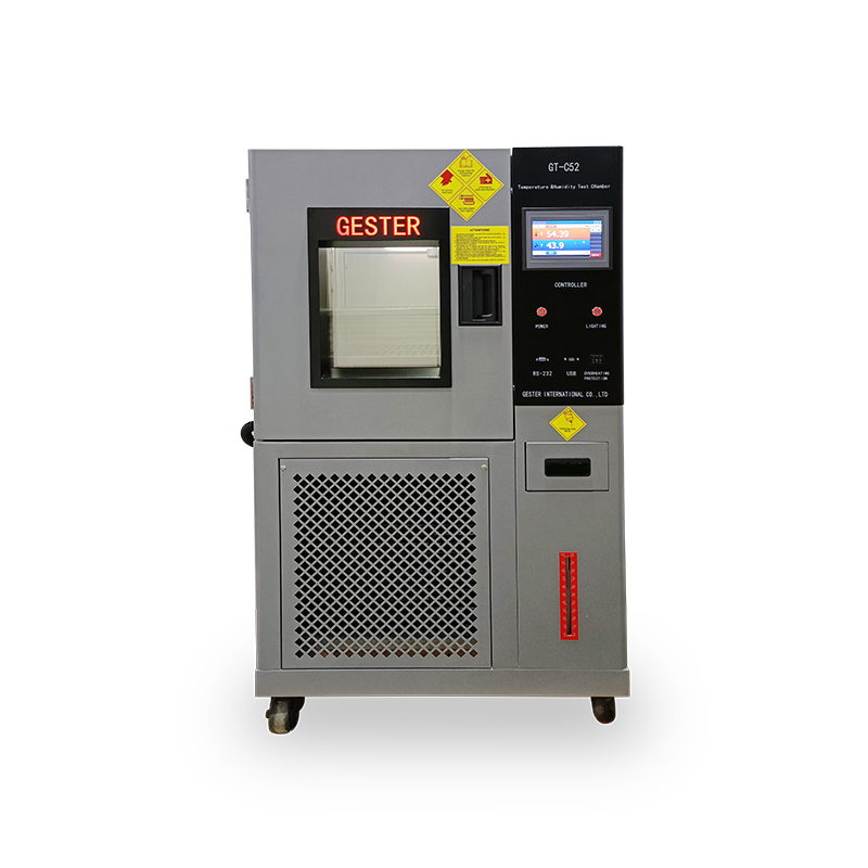
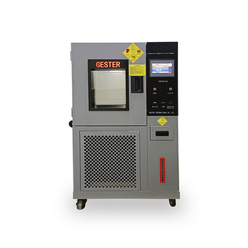
High-Precision Climate Simulation for Reliable Material & Electronic Reliability Testing -This constant temperature humidity chamber features programmable control, wide temperature and humidity ranges, and complies with international standards. Main Features: ✔ Wide Testing Range: Temperature: -60°C to +150°C | Humidity: 20% to 98% RH. ✔ Smart Control: 7-inch programmable color touch screen controller with USB data export. ✔ Premium Components: Equipped with imported French Tecumseh compressor. ✔ International Standards: Fully complies with ISO, ASTM, IEC, JIS, BS.
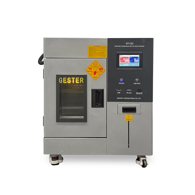
Benchtop temperature and humidity test chamber delivers precise environmental control through stable temperature and humidity settings for conditioning of samples prior to testing. Its compact footprint allows it to be easily placed on a stand or workbench, perfectly suiting laboratories and testing areas where space is limited — without compromising build quality or testing performance.
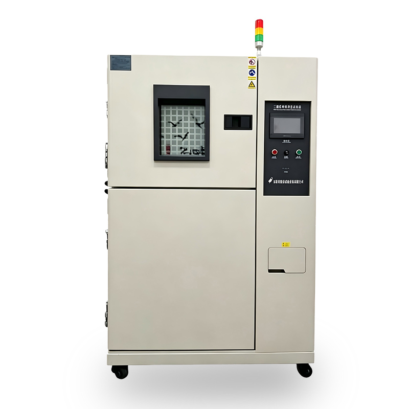
Thermal Shock Test Chamber consists of two independent compartments. The thermal shock machine or material being tested is placed in a test basket or tray and then transferred between the hot and cold chambers. The transfer process is rapid, ensuring quick temperature changes that simulate real-world conditions. This enables manufacturers to evaluate the impact of temperature differentials on product integrity, performance, and reliability.
High Low Temperature Test Chamber is devices specifically designed to simulate extreme high- and low-temperature environments, enabling the assessment of the durability, functionality and performance of materials and components following prolonged exposure. Ideal for material durability testing in electronics, aerospace, and industrial applications.
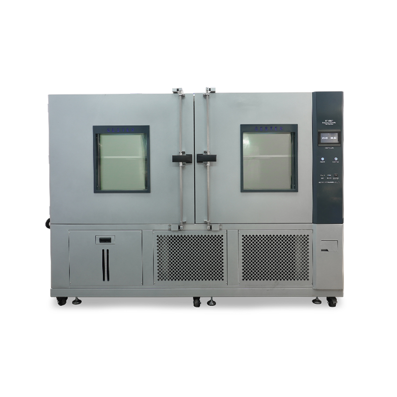
Walk In Environmental Test Chamber, suitable for test instrumentation materials, electricians, electronic products, household appliances, auto parts, chemical coatings,various electronic components and parts of other related products are stored and transported under high temperature and low temperature environment. The adaptability test is used to evaluate its performance indexes.
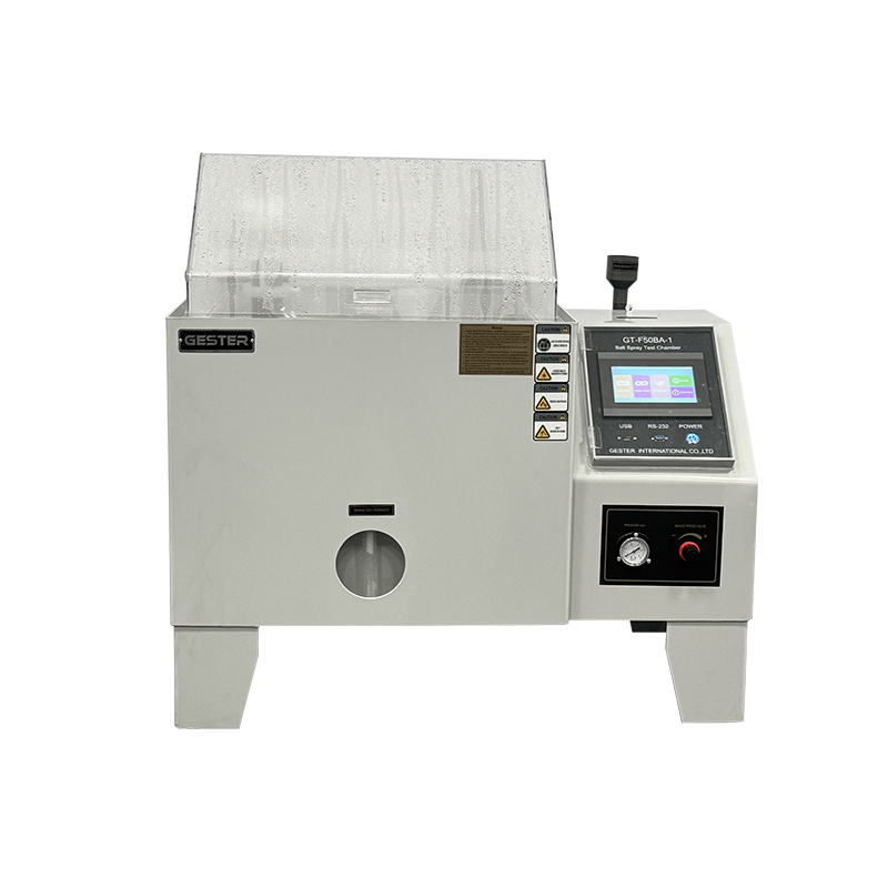
Salt spray test chamber is essential for evaluating the corrosion resistance of metals, coatings, and other materials – ensuring that products meet stringent corrosion resistance standards and enhancing their reliability in real-world applications.
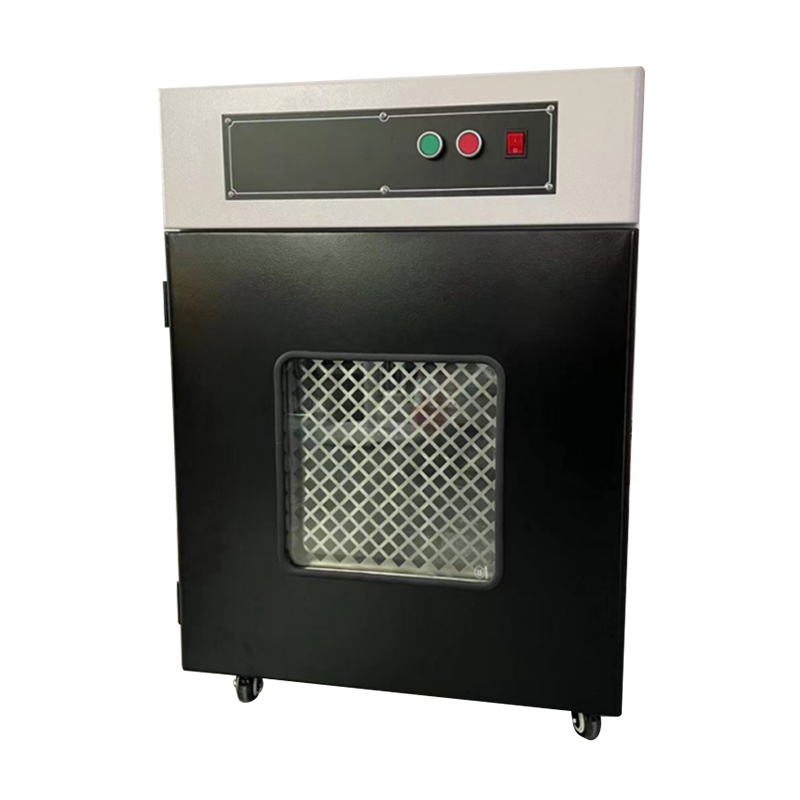
The Battery Overcharge and Overdischarge Explosion-Proof Test Chamber GT-I08 is a specialized safety testing enclosure designed for evaluating battery performance under extreme charging and discharging conditions. Main Features: ✔ Comprehensive Safety Protection System ✔ Precision Temperature Management ✔ Durable Explosion-Proof Structural Design ✔ Real-Time Safety Monitoring ✔ Wide Compatibility & Easy Operation
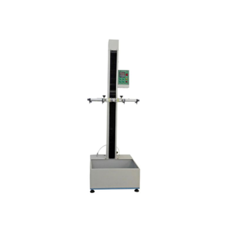
This Battery Pack Drop Testing Machine is suitable for free fall testing of small consumer electronic products and components such as mobile phones (cell phones), mobile phone lithium batteries, walkie-talkies, electronic dictionaries, building intercom phones, CD/MD/MP3 players, etc. Precision testing, powering safety • Accurate drop control • Enhance battery safety • Reliabletest results • Easy to usesmart control
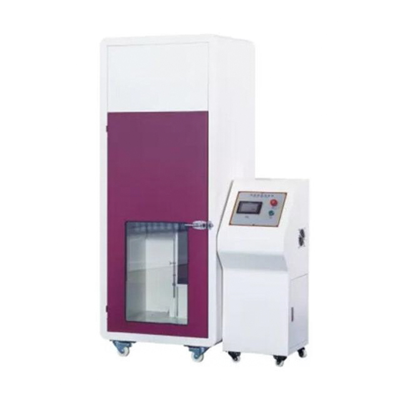
GESTER is the Professional Battery Nail Penetration Testing Machine manufacturer.
This Battery Nail Penetration Testing Machine is designed to simulate conditions where various types of batteries are subjected to sharp object penetration during use, transportation, storage, or disposal as household waste.The battery is considered qualified if no explosion or fire occurs during the test. Standards GB/T 18332.2, QC/T 743, YDT 2344.1, YDT 2344.2, QC/T 744
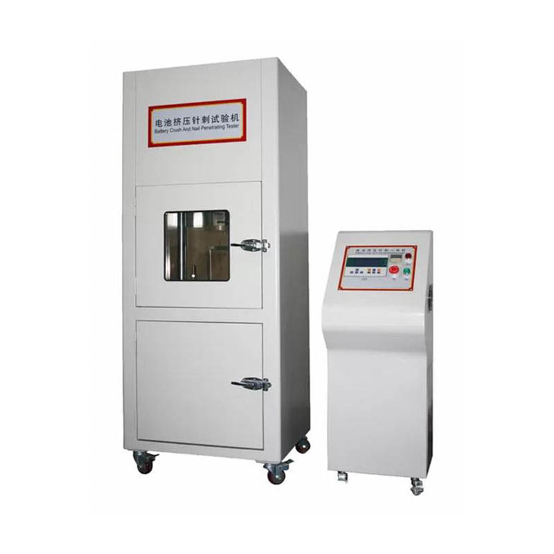
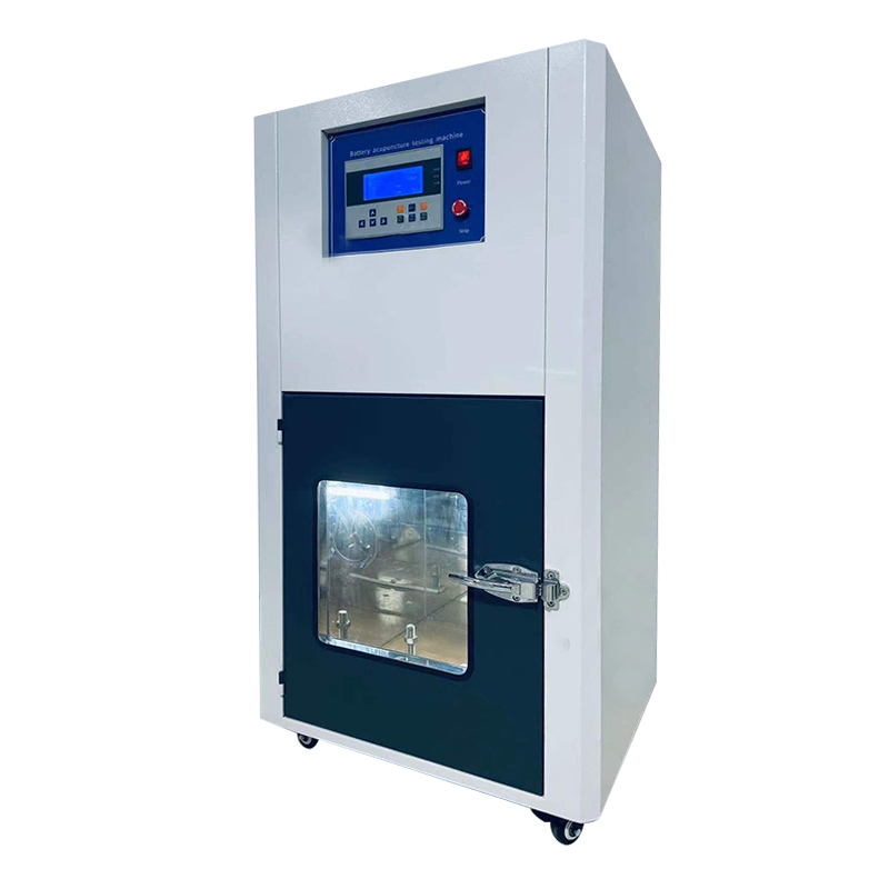
The battery squeeze and acupuncture integrated machine inspects the safety performance of the battery through the squeeze test or acupuncture test, and judges the test result through real-time test data (such as battery voltage, the highest temperature of the battery surface, and the pressure video data).
leave a message
Scan to wechat :

Scan to Whatsapp :